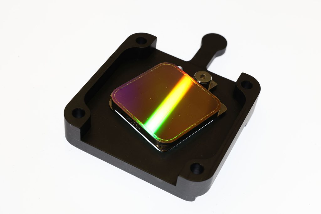
Simple theoretical treatments of grating diffraction efficiency usually distinguish between amplitude gratings (which consist of transparent gaps between fully absorbing or opaque grating bars) and phase gratings (which consist of two regions of differing phase shifts upon transmission or reflection). Scalar Kirchhoff diffraction theory in the Fraunhofer limit shows that the maximum efficiency in +/- 1st diffraction orders is (1/π)2, or about 10%, for amplitude gratings, while for phase gratings it can theoretically be up to four times larger, if the phase shift between the two regions is equal to π.
In reality, most gratings are a mix between amplitude (there are always losses) and phase gratings. One of the difficulties of making an efficient phase grating for x rays is that the index of refraction n for all materials is very close to one (|n – 1| = 10-2 – 10-4), which means that a π phase shift requires grating bars that are orders of magnitude taller than the x-ray wavelengths. Transmitting through many wavelengths of material leads to absorption, reducing diffraction efficiency. At the same time, grating period shouldn’t be more than ~ 102 times the x-ray wavelength, to produce sufficiently large diffraction angles. These demands call for sub-micron period, high aspect-ratio grating bars made of electron-dense material.
Under these constraints (and many others), Schattenburg et al. in the late 80’s and early 90’s developed the design and fabrication methods for the Medium and High Energy Gratings (MEG and HEG) for the High Energy Transmission Grating Spectrometer (HETG) on the Chandra X-ray Observatory. A detailed description is given by Canizares et al.
In brief, the gratings are made of gold bars (400 and 200 nm period, 360 and 510 nm tall), supported by a thin polyimide membrane. The initial pattern is generated using UV interference lithography. The grating parameters were chosen for peak efficiency near 1.5 – 2 keV, where the gratings are close to 20% efficient in +/- 1st orders, and over 10% efficient up to 6 keV.